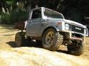
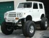
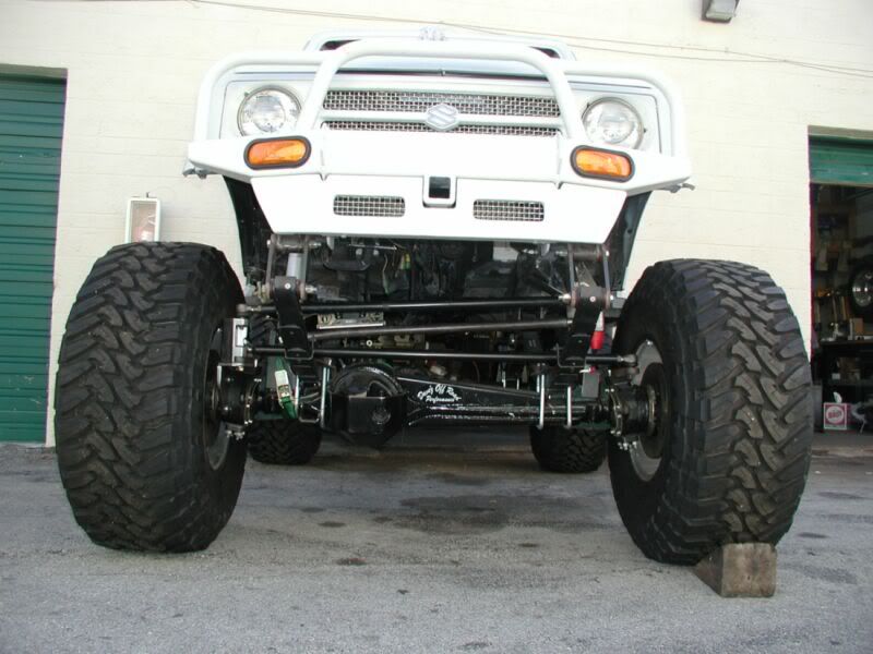
Zuk on 38's
Re: Zuk on 38's
From one zuker to another. Thanks for sharing this amazing build. And I didnt know till now jeep made cars. Thanks again.
Latest mod, pin stripes, hit the same branch I did on the way in on the way out.
ford ranger wildtract and sj.
ford ranger wildtract and sj.
-
PuddleJumper
- Hard Yaka
- Posts: 204
- Joined: Fri Mar 03, 2006 12:00 pm
Re: Zuk on 38's
Nice truck!
I have a factory LWB Zuk ute thats got a few mods.. Not even close to being in the same league as this though
Looks like it was rust free bodywise. Will this be street legal once you've finished?
Very
I have a factory LWB Zuk ute thats got a few mods.. Not even close to being in the same league as this though
Looks like it was rust free bodywise. Will this be street legal once you've finished?
Very
Re: Zuk on 38's
PuddleJumper wrote:Nice truck!
I have a factory LWB Zuk ute thats got a few mods.. Not even close to being in the same league as this though
Looks like it was rust free bodywise. Will this be street legal once you've finished?
Very
Like the LWB the UTE are very hard to find in the US. Usually end up with a ruty one from Canada.
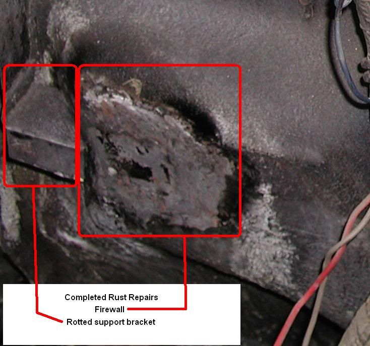
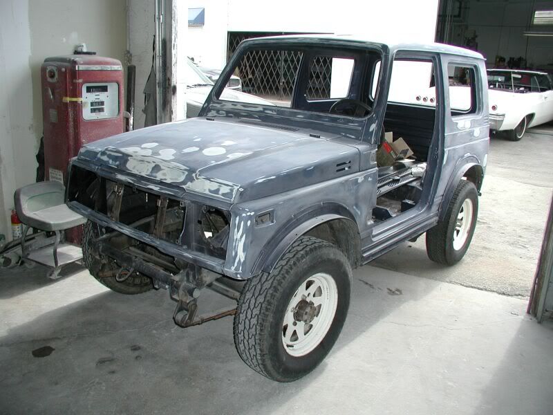
This one was purchase from California and it had very little rust. The PS fender was bad from the battery acid from the older style batteries. There was also a 7"x5" patch for the firewall for the same reason.
I will post some pics of the body work shortly along with a few pics of my DD TT that is much more conservative.
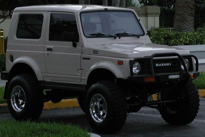
Yes, the Rig will be street legal where I live there are a few in my area already. As long as you are not being an idiot on the road they leave you alone. However I would have issues in other parts of Florida and crossing the state line which will never happen any way.
Thanks for the questions and taking the time to stop in.
Re: Zuk on 38's
007 wrote:From one zuker to another. Thanks for sharing this amazing build. And I didnt know till now jeep made cars. Thanks again.
Thanks for taking a look, nice to see the zukers are stopping in.
If you are interested in looking at more Willys Hotrod cars.
Here is a Link:
http://www.carnut.com/photo/list/willys.html
Re: Zuk on 38's
Here is a pic of my DD TT next to the big one for comparison. It is more conservative with mostly store bought goodies.
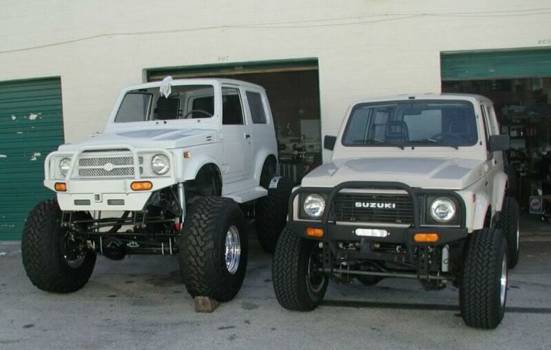
DD Stats: SPUA, AC, 1.3, 31's, 10" rims, Toy 2TC Carb, 4" Hell Creek springs, Cal Mini Shackle reverse, 1.25" spacers, 4.9 Transfer case gears, Zor snatch, Sky half OTT Steering and Mostly Original paint.
Had the hood and the back door repainted and replaced the rear door hinges
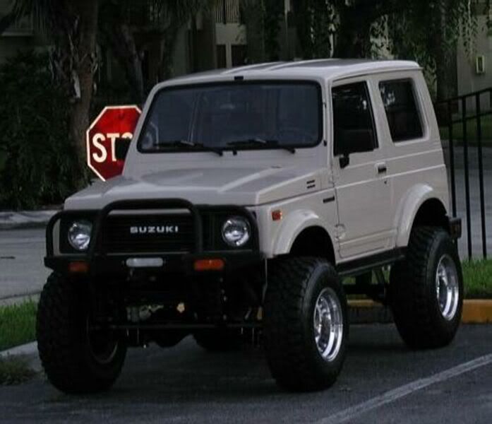
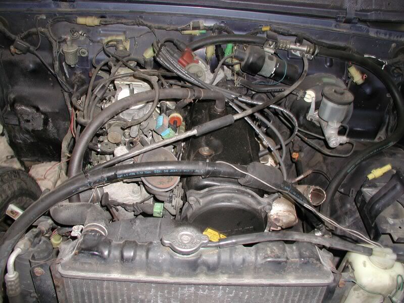
2TC Toy Carb

Will be glad to answer any questions on the DD.
DD Stats: SPUA, AC, 1.3, 31's, 10" rims, Toy 2TC Carb, 4" Hell Creek springs, Cal Mini Shackle reverse, 1.25" spacers, 4.9 Transfer case gears, Zor snatch, Sky half OTT Steering and Mostly Original paint.
Had the hood and the back door repainted and replaced the rear door hinges
2TC Toy Carb
Will be glad to answer any questions on the DD.
Re: Zuk on 38's
Here is some info on the 2TC carb for another alternative:
1978-79 COROLLA 3KC
1166 CC ENGINE 4 CYL
2 BBL AISAN
Carb PN TOY-250
There was a noticeable improvement over the stock carb. The carb worked with out any trouble rite out of the box. There is none of the Weber issues on offroading and I get 24MPG.
We don’t use the SU over here they are too expensive and too hard to find. My buddy has the Weber and his is stock and my DD on 31’s keeps up with it and seems to get a bit better gas mileage as well.
Here are a few links on how to do the Mod.:
Caution: it is not as straight forward as it seems. I did give this info to someone on the Zuwharrie a few months ago and he loves it.
http://www.acksfaq.com/toycarbinstall.htm
http://bbs.zuwharrie.com/content?P=30a1 ... ic=25544.0
http://bbs.zuwharrie.com/content?P=30a1 ... ic=85345.0
Re: Zuk on 38's
Lessons Learned
When I got the DD it was a mess with a bad lift. I decided to buy the suspension lift components that were at Calmini and Hell Creek.
I decided to leave it spring under because I was afraid to weld on the thin axle tubes and it was suppose to handle better in this position. With the lift add I need to remove the sway bar which seems to be the thing to do from the reading I did.
My experience with the parts that were added.
Calmini SR lift: I will be removing it in the near future. I do not care the way the front tends to nose dive under braking. The axle now pushes to the fire wall and this will cause the tire to bump the firewall if wheeled hard. You will also have to shim the caster angle back in.
When I did my research the SR was suppose to be the better way to go. Not in my opinion.
Hell Creek Lift Springs: These were recommended for spring under axle use. When I installed them they were not centered in the wheel arches. This is why I added the Calmini SR. This added 2” more lift and also pushed the axle forward an 1”. This gave me enough room for tire clearance and the tires were now centered in the arch.
The suspensions is fine in the city. There is a big problem on the interstate at speed when it is windy. I do not use the interstate any more just the 2nd dairy roads for this reason.
I’m sure there are others that have learned what they will do the next time around. This is why I’m going to take the SR off. Put the sway bar back on and use the regular shackles in the front position again. I will still leave it spring under axle but I will re drill the locating hole for the leaf springs to push the axle forward an 1”.
I hope that will give me a more all around vehicle
Re: Zuk on 38's
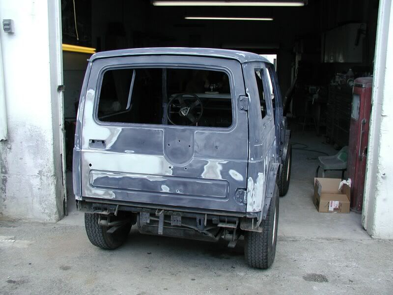
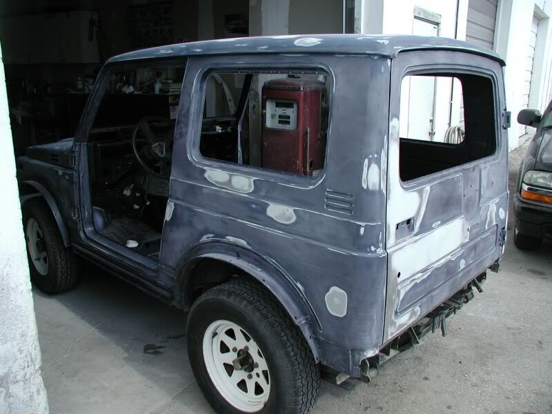
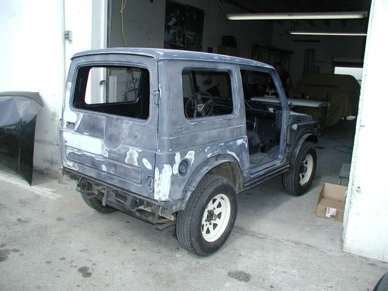
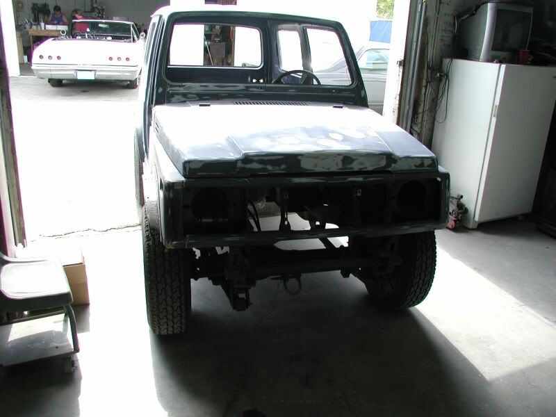
Rust Repair
It is tough to find a vehicle that is 25 years old that doesn’t have a bit of rust some place. Even though this Zuk was bought in California which is a good place for rust free vehicles there was still some rust.
I had to replace the fender and do an extensive repair of the firewall and a support bracket for the inner fender that had rotted away from battery acid. Here are some pics of the strip down, repair and reassembly.
Here is the fender off
Repaired areas
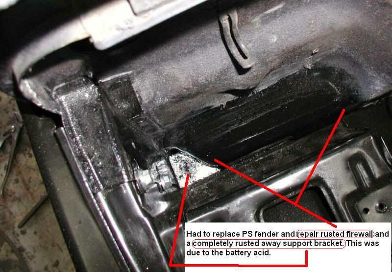
Inside of replaced fender
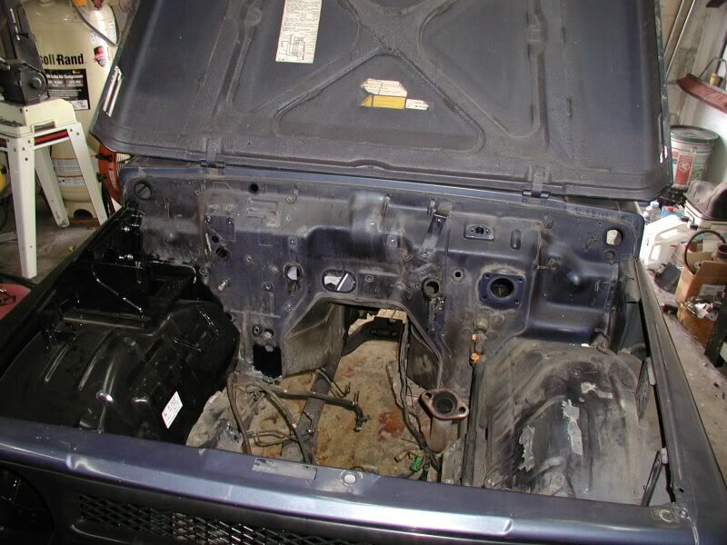
New fender and Updated Grill
I’m sure that most can relate to this pic
It is tough to find a vehicle that is 25 years old that doesn’t have a bit of rust some place. Even though this Zuk was bought in California which is a good place for rust free vehicles there was still some rust.
I had to replace the fender and do an extensive repair of the firewall and a support bracket for the inner fender that had rotted away from battery acid. Here are some pics of the strip down, repair and reassembly.
Here is the fender off
Repaired areas
Inside of replaced fender
New fender and Updated Grill
I’m sure that most can relate to this pic
Re: Zuk on 38's
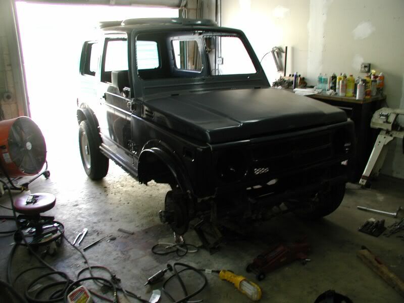
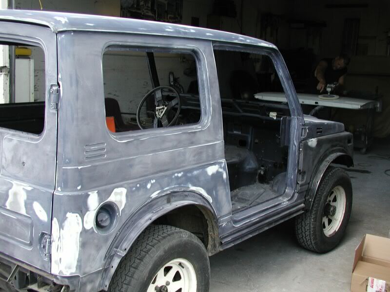
Paint and Body Repair
Re: Zuk on 38's
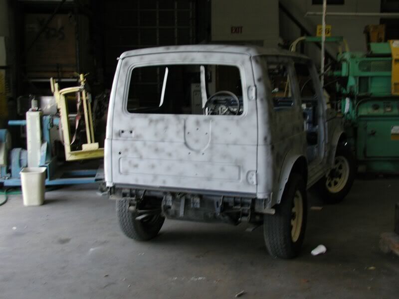
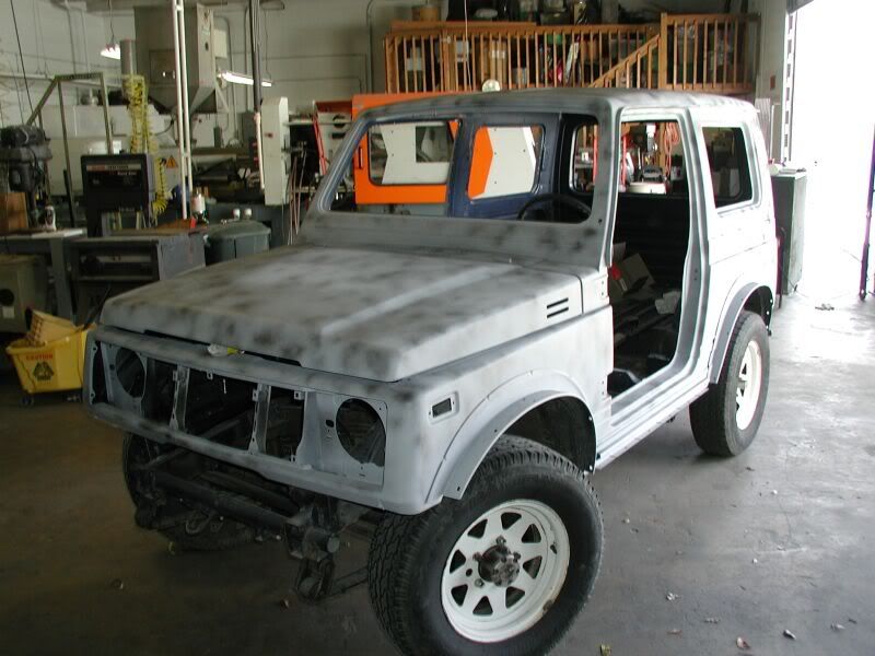
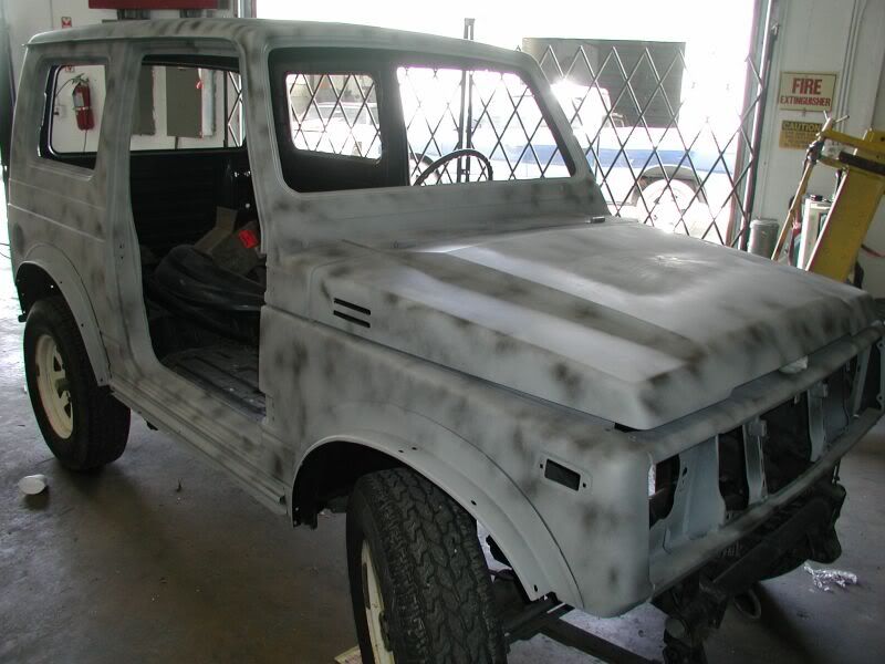
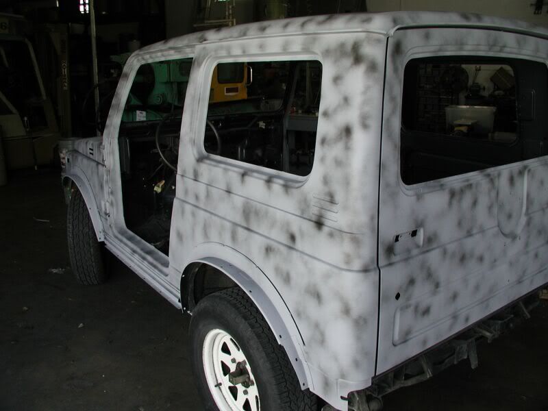
The Zuk is over my buddy shop across from the painter. The primer is on and fogged with the darker color for the finish sand and checking for low spots.
Re: Zuk on 38's
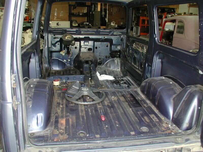
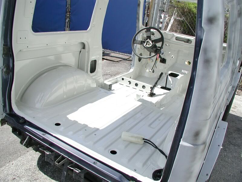
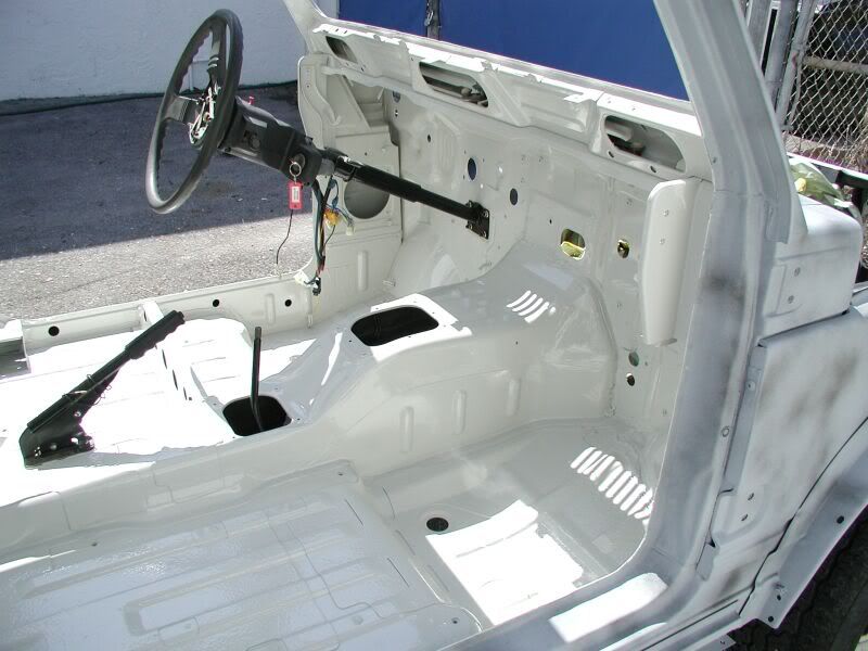
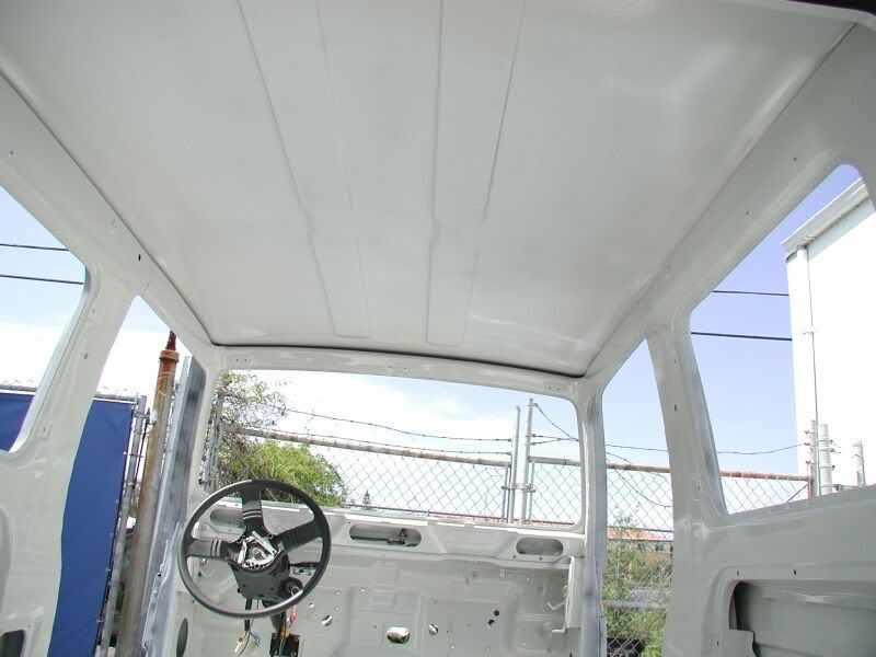
Here is the inside being painted. This is the last of the body and paint pics that I have.
Re: Zuk on 38's
Here are a couple of products I use to prevent the rust from coming back on a proper patch work. Ospho is a liquid metal prep used after you have done your patch repair( Welded In Patch). Then I use POR 50 this is a black sealant coating that is used to prevent moisture from getting back into the area to start the rust process again. I showed a pic of the firewall repair the black color was the POR 50.
The POR 50 is a bit of a PITA to use though. Once you open the can you really need to use it all at one time. Don't get any on your skin ( Use Gloves ) and you will have to throw away any brushes used. I prefer to get the small I believe it is a 3 ounce can then there is not that big of a problem using it up.
I can’t take credit for the paint. I paid to have this one painted. Just had too much to do with the mods, engine rebuilding, machining up new parts, new inlet and everything that was old or damaged to take that on too.
I can how ever answer some of your questions becuase I do body work when it is needed.
The gray color is a primer sealer. This is used after repair work is done and for sealing the old paint in so it doesn't bleed through your new paint.
The Fogged in color which is just some cheap black paint. This is used to see any low spots when you use a long board to sand the body with. If you are getting a ruff surface you will need to step down your sanding grits until it is better. It is better to use the long board which spreads the sanding in a much larger area and you will be able to do a much better job on the body work.
Ospho and POR 50 used on this repair
Here is a Link to the Sanding Boards
http://dura-block.com/durablockline.html
Re: Zuk on 38's
Here is a tip that I do as maintenance to keep the rust down on the DD.
Every couple of weeks I go around the DD and look for any new little spots of rust where there has been paint chipped away for one reason or another. This is because most of the paint is still original and because I live in Florida and the salt issue.
I use a small paint brush and dab some Ospho rust inhibitor on the surface rusted area. I let that dry until it changes the rust color to a grayish color. Then I use another small paint brush and put some touch up paint on it.
This works very well. I had several small spots on the DD when I got it 3 years ago and nothing has gotten any worse. In fact the spots that I took care of then still look good.
Re: Zuk on 38's
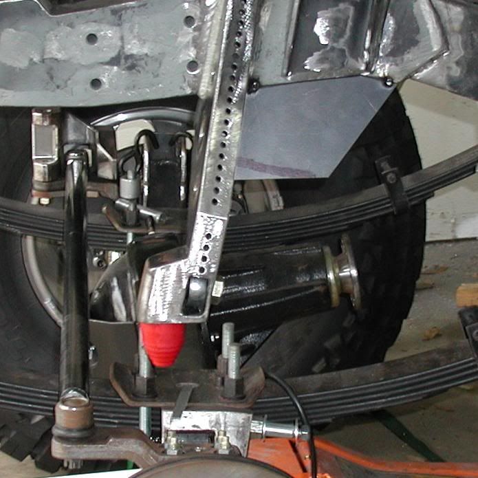
Ok, enough of that here is some more fab work
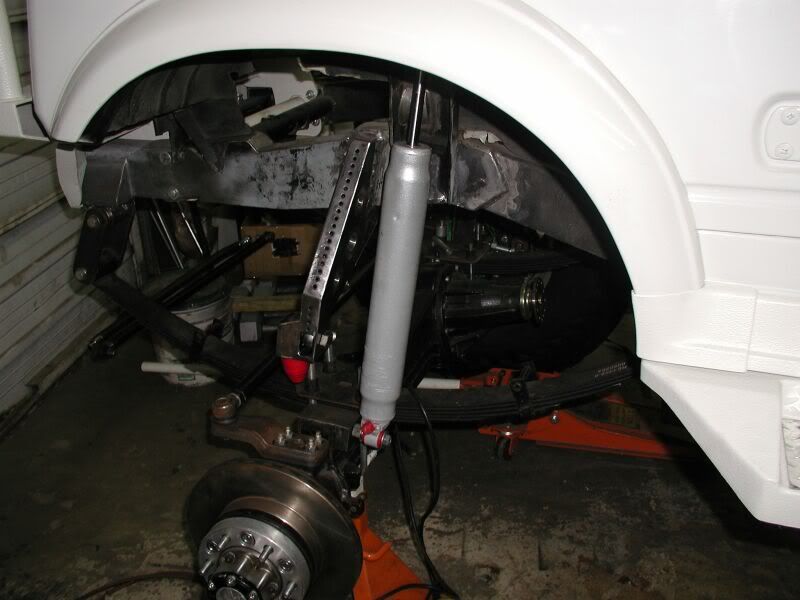
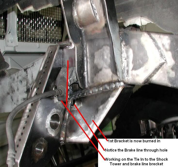
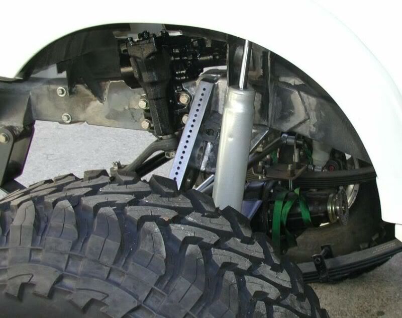
Burned in the Panhard/Bumpstop mount in at 12*
Burned in the Modified Ford Shock Tower at 8*
The lower portion of the Bumpstop mount was boxed in. This was to conceal the nuts holding the Heim Joint and the Bumpstop in place. This will also give it more strength and add an additional place for a support bracket for the 1.25 DOM Front Brace Tube.
Working on the bracket that is on the shock side of the mount. This has many compound angles and will be a full box. I will also try and add some holes with support tubes.
Re: Zuk on 38's
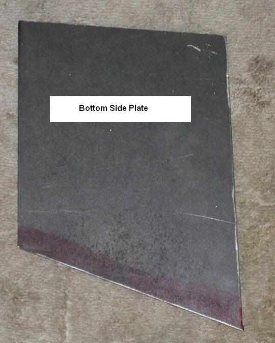
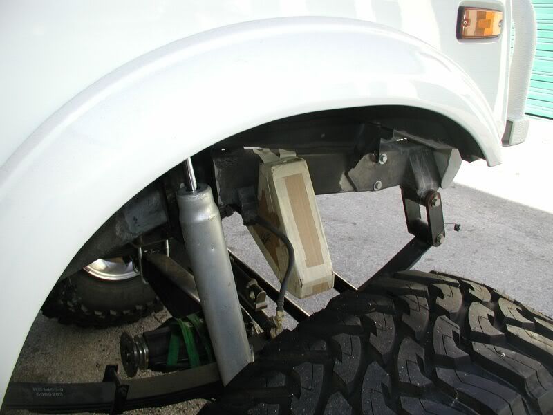
Panhard Mount Bracket being made. This is the 1st of 3 brackets.
This is the lager bracket and will be partially concealed with the shock. This will make it not as noticeable.
Steps:
Starting pieces needed to be tacked in place because of their irregular shape.
Matting box pieces will be fitted and welded in place.
Bracket will then be removed to weld the inside
Holes will be popped in and support tubes added while it is out.
Final Bracket burn in
Note: Rear side plate still needs to be made to complete the full boxed bracket..
Re: Zuk on 38's
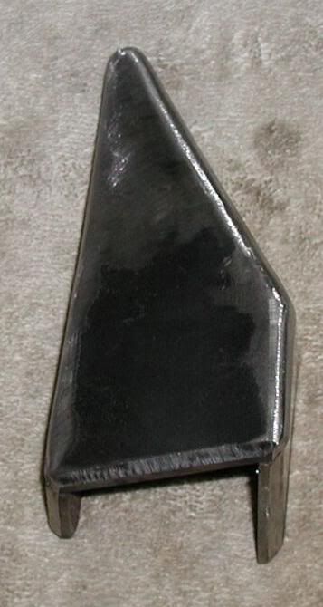
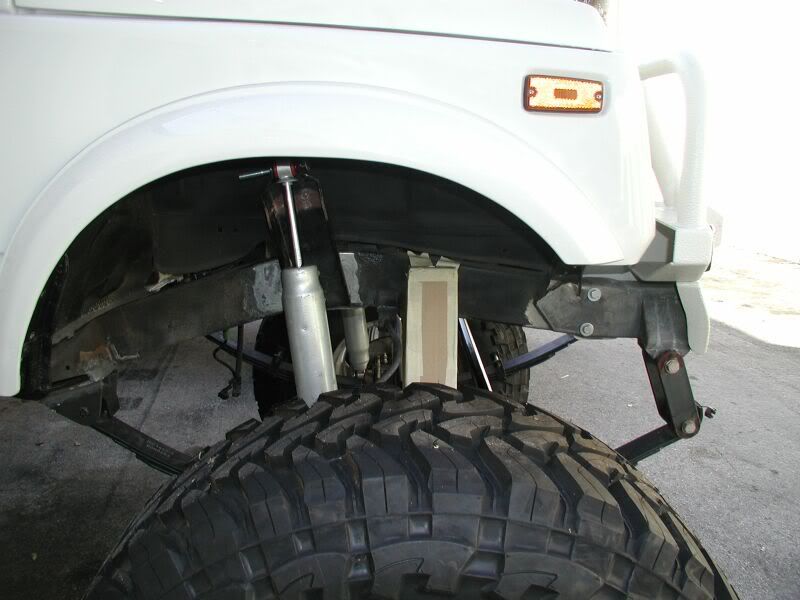
This has been an interesting bracket to make. There were no parallel surfaces on any of the pieces and there were a few compound angles. The shapes looked more like a kite then a bracket.
The first 2 steps are done.
Steps:
Starting pieces needed to be tacked in place because of their irregular shape.
Mating box pieces will be fitted and welded in place.
Bracket will then be removed to weld the inside
Holes will be popped in and support tubes added while it is out.
Final Bracket burn in
The pieces will be welded together while it is still on the frame. The tacks will then be cut off the frame to make it easier to work on bracket for the holes, installing the support tubes and weld the inside for strength.
Re: Zuk on 38's
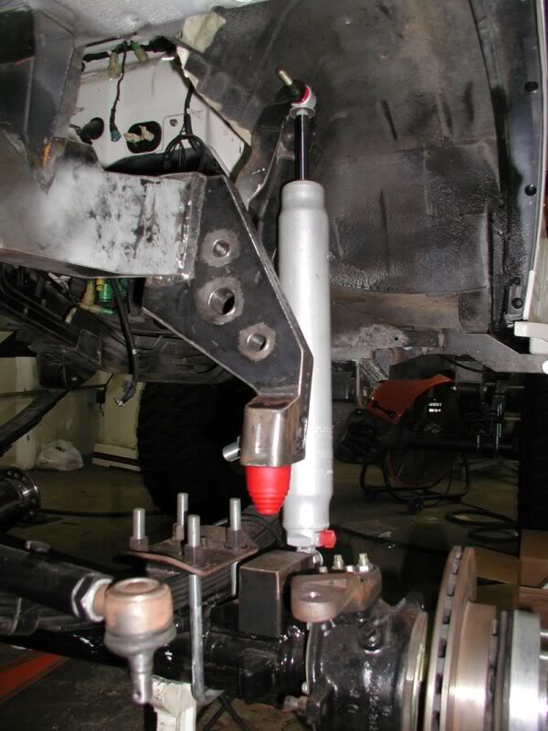
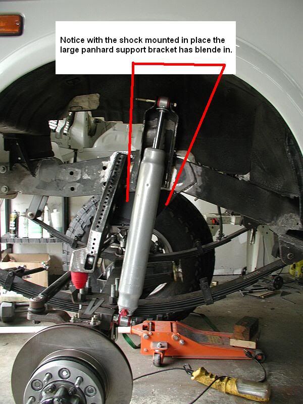
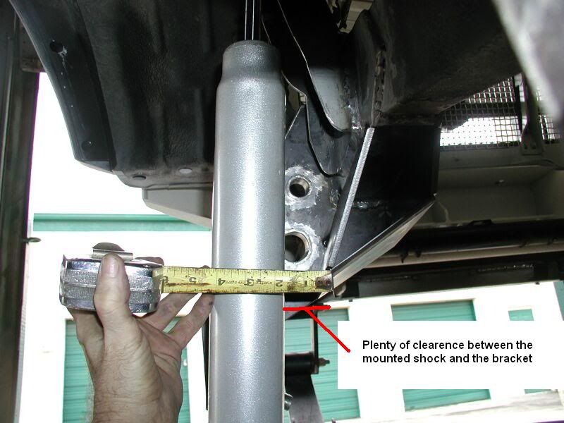
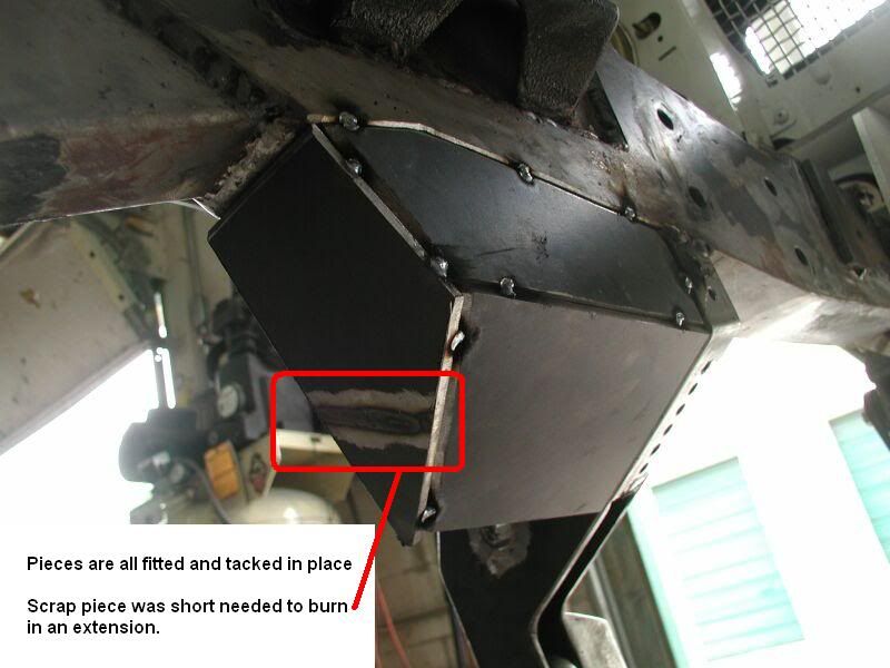
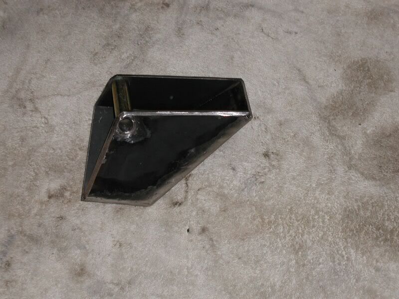
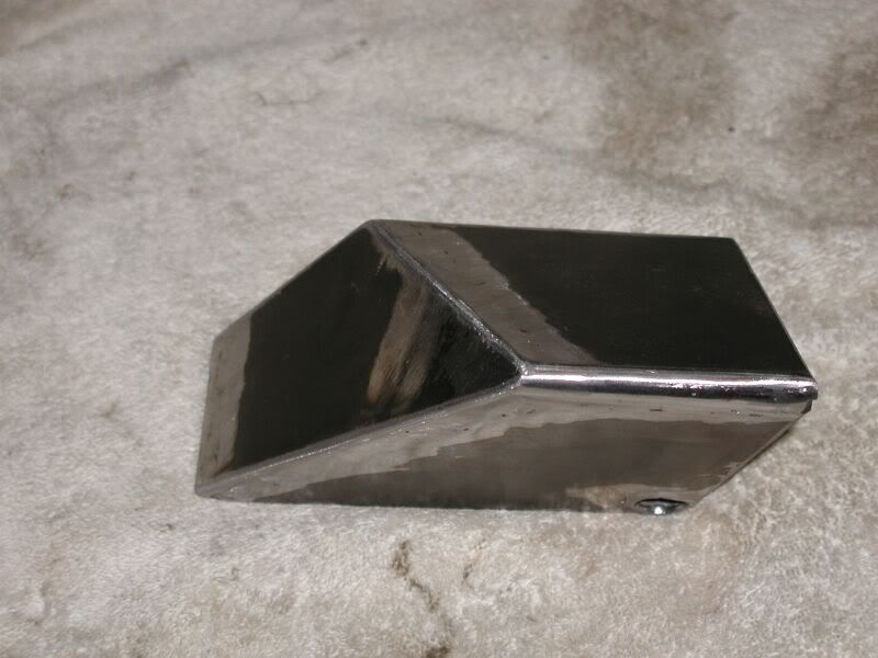
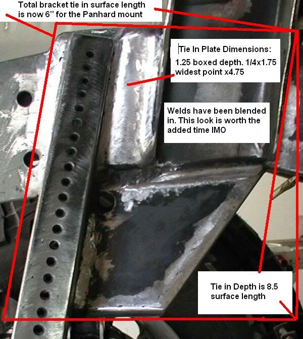
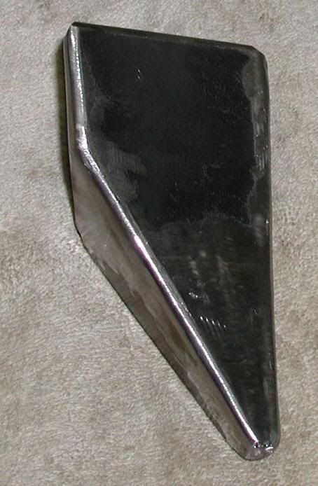
Here is a look at the large Panhard bracket which is a perfect example of a 3D trapezoid.
It took a little longer to complete after collaborating with Jethrobodean on the best structural strength of the bracket location. He had pointed out with the bracket blending in at the end of the fishplate. This would cause extra stress on this area. The better option would be to keep it 1 to 1.5” away from the end of the fishplate.
The choice was the shorter route to correct the problem because the plates were made already. The new position just happened to be my original thought. The strong need to make it more visually pleasing with everything blending at one place just took over.
Jethrobodean also mentioned to add a fishplate to the backside of the bracket where it is being welded to the frame. This will be done as a precaution to eliminate the possibility of excess stress on this area. There was also mention to tie the top of the Panhard mount to the Ford Shock Tower for additional strength. All these were very good suggestions and will be performed as well.
Very Big Thanks to Jethrobodean for taking the time to point out something that I had contemplated on or over looked. It is always good to have an extra set of eyes looking at a complex design to accomplish the best out come.
Again it is better to be flexible ask for some input and make corrections on your design. This may require reworking or scrapping something that took a long time to make to address an issue.
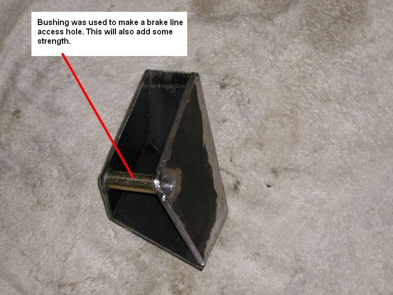
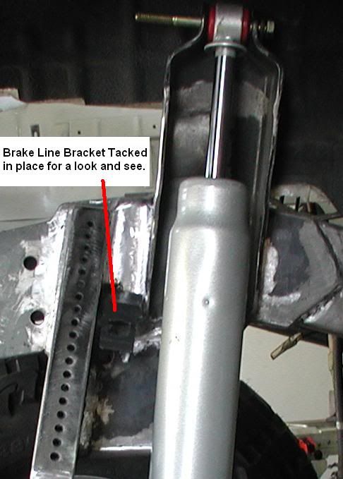
You may be wondering why the tube bushing. It has been about 9 months or so since the original brackets were removed. Good thing I had remembered that the steel brake line had to have away to get to the brake line bracket. The tube seemed to be a good solution and give some more strength to the bracket.
It took a little longer to complete after collaborating with Jethrobodean on the best structural strength of the bracket location. He had pointed out with the bracket blending in at the end of the fishplate. This would cause extra stress on this area. The better option would be to keep it 1 to 1.5” away from the end of the fishplate.
The choice was the shorter route to correct the problem because the plates were made already. The new position just happened to be my original thought. The strong need to make it more visually pleasing with everything blending at one place just took over.
Jethrobodean also mentioned to add a fishplate to the backside of the bracket where it is being welded to the frame. This will be done as a precaution to eliminate the possibility of excess stress on this area. There was also mention to tie the top of the Panhard mount to the Ford Shock Tower for additional strength. All these were very good suggestions and will be performed as well.
Very Big Thanks to Jethrobodean for taking the time to point out something that I had contemplated on or over looked. It is always good to have an extra set of eyes looking at a complex design to accomplish the best out come.
Again it is better to be flexible ask for some input and make corrections on your design. This may require reworking or scrapping something that took a long time to make to address an issue.
You may be wondering why the tube bushing. It has been about 9 months or so since the original brackets were removed. Good thing I had remembered that the steel brake line had to have away to get to the brake line bracket. The tube seemed to be a good solution and give some more strength to the bracket.
Re: Zuk on 38's
Burned in the Panhard/Bumpstop mount in at 12*
Burned in the Modified Ford Shock Tower at 8*
The lower portion of the Bumpstop mount was boxed in. This was to conceal the nuts holding the Heim Joint and the Bumpstop in place. This will also give it more strength and add an additional place for a support bracket for the 1.25 DOM Front Brace Tube.
Working on the bracket that is on the shock side of the mount. This has many compound angles and will be a full box. I will also try and add some holes with support tubes.
Re: Zuk on 38's
Panhard Mount Bracket being made. This is the 1st of 3 brackets.
This is the lager bracket and will be partially concealed with the shock. This will make it not as noticeable.
Steps:
Starting pieces needed to be tacked in place because of their irregular shape.
Matting box pieces will be fitted and welded in place.
Bracket will then be removed to weld the inside
Holes will be popped in and support tubes added while it is out.
Final Bracket burn in
Note: Rear side plate still needs to be made to complete the full boxed bracket..
Re: Zuk on 38's
This has been an interesting bracket to make. There were no parallel surfaces on any of the pieces and there were a few compound angles. The shapes looked more like a kite then a bracket.
The first 2 steps are done.
Steps:
Starting pieces needed to be tacked in place because of their irregular shape.
Mating box pieces will be fitted and welded in place.
Bracket will then be removed to weld the inside
Holes will be popped in and support tubes added while it is out.
Final Bracket burn in
The pieces will be welded together while it is still on the frame. The tacks will then be cut off the frame to make it easier to work on bracket for the holes, installing the support tubes and weld the inside for strength.
The first 2 steps are done.
Steps:
Starting pieces needed to be tacked in place because of their irregular shape.
Mating box pieces will be fitted and welded in place.
Bracket will then be removed to weld the inside
Holes will be popped in and support tubes added while it is out.
Final Bracket burn in
The pieces will be welded together while it is still on the frame. The tacks will then be cut off the frame to make it easier to work on bracket for the holes, installing the support tubes and weld the inside for strength.
Re: Zuk on 38's
Here is a look at the large Panhard bracket which is a perfect example of a 3D trapezoid.
It took a little longer to complete after collaborating with Jethrobodean on the best structural strength of the bracket location. He had pointed out with the bracket blending in at the end of the fishplate. This would cause extra stress on this area. The better option would be to keep it 1 to 1.5” away from the end of the fishplate.
The choice was the shorter route to correct the problem because the plates were made already. The new position just happened to be my original thought. The strong need to make it more visually pleasing with everything blending at one place just took over.
Jethrobodean also mentioned to add a fishplate to the backside of the bracket where it is being welded to the frame. This will be done as a precaution to eliminate the possibility of excess stress on this area. There was also mention to tie the top of the Panhard mount to the Ford Shock Tower for additional strength. All these were very good suggestions and will be performed as well.
Very Big Thanks to Jethrobodean for taking the time to point out something that I had contemplated on or over looked. It is always good to have an extra set of eyes looking at a complex design to accomplish the best out come.
Again it is better to be flexible ask for some input and make corrections on your design. This may require reworking or scrapping something that took a long time to make to address an issue.
You may be wondering why the tube bushing. It has been about 9 months or so since the original brackets were removed. Good thing I had remembered that the steel brake line had to have away to get to the brake line bracket. The tube seemed to be a good solution and give some more strength to the bracket.
Re: Zuk on 38's
Here is my old school cardboard 2D cad mock up of the 1.25 DOM radius support bracket.
The specs are:
1.25 DOM Dia. 1/4 wall with a 4.5” inner radius at 90*.
Bottom support bracket 3/8
Top support brackets ¼ (2)
There will still be a front bracket added. Working on the pieces now.

The specs are:
1.25 DOM Dia. 1/4 wall with a 4.5” inner radius at 90*.
Bottom support bracket 3/8
Top support brackets ¼ (2)
There will still be a front bracket added. Working on the pieces now.
Re: Zuk on 38's
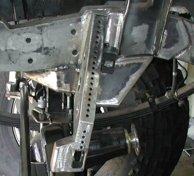
Front Side 2nd Bracket is made and welded in place. You can now see the extensive amount of surface area the brackets use for strengthening the Panhard Mount. There will still be the additional 3rd round bar bracket. With all three brackets in these positions will equally distribute the load on the frame.
There will also be an additional Tie in1.25 Heim joint bar mounted between the bumpstop mounts on both sides. This will transfer any additional loads to both sides of the frame for even more strength.
Some I’m sure had some doubt of this actually working out. Hope that these Brackets and Tie in’s have helped in changing your minds.
Re: Zuk on 38's
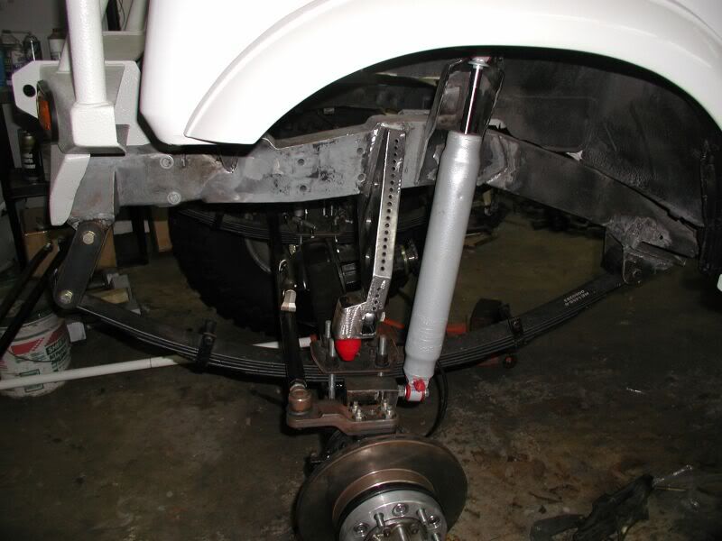
This is the steering link and panhard bars set at 3 ½ degrees. With all the mods made the steering is now close to stock geometry.
Waiting on the DS 1.25 DOM tube to be bent and that will finish this side up.
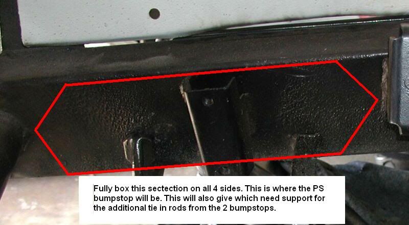
Made my old school cardboard 3D cad mock up for the PS bumpstop.
Waiting on the DS 1.25 DOM tube to be bent and that will finish this side up.
Made my old school cardboard 3D cad mock up for the PS bumpstop.
Re: Zuk on 38's
We are now on real time for the build so updates will be a bit slower now.
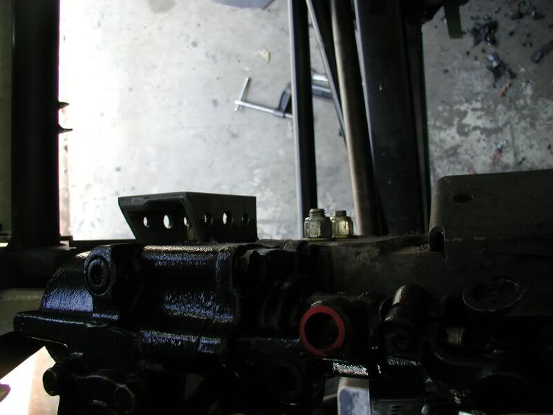
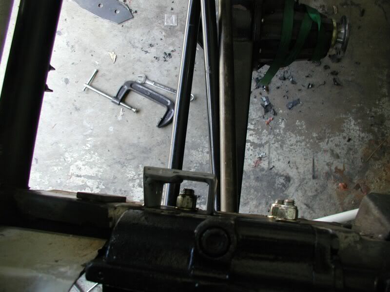
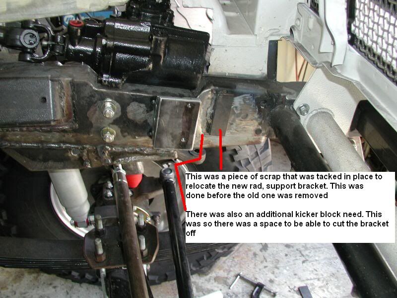
While working on boxing in the PS frame rail the rad support bracket was going to have to be removed. The DS bracket was also removed during the same process earlier. Before the removal of PS bracket the DS bracket needed to be made and reattached. This was to keep the 2 bracket oriented properly.
The process and a couple of tips for this bracket install.
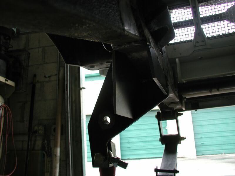
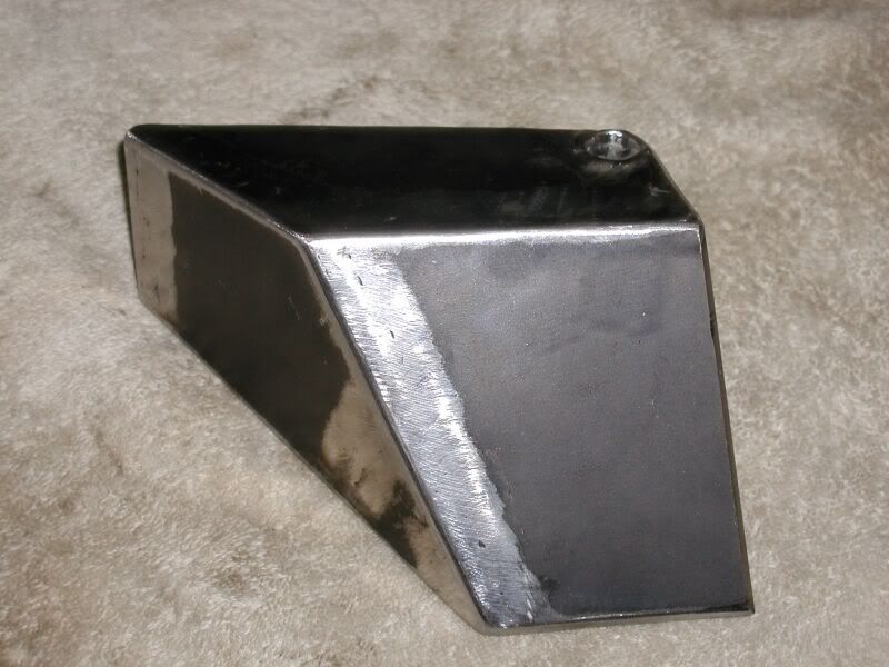
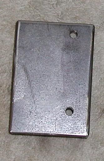
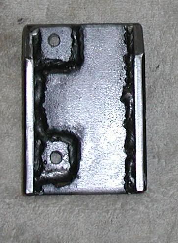
Here is the DS radiator support bracket. This had to be remade because of the new location of the lock nuts for the FJ80 box. The box was also dropped an inch resulting
in chopping the frame down.
These 2 obstacles were a bit of an issue. This bracket needed to be made and installed before the PS inside rail was stripped of the radiator support bracket for the boxing in process.
The bracket was made of ¼” plate and 2 small pieces of ¼” plate were added to make a thicker pad for threading. To make up for the missing inch from the upper frame for mounting the bracket was made 1” longer and the top was given angle cuts to blend in to the frame. The bracket was also made 1” wider to go over the lock nuts.
While working on boxing in the PS frame rail the rad support bracket was going to have to be removed. The DS bracket was also removed during the same process earlier. Before the removal of PS bracket the DS bracket needed to be made and reattached. This was to keep the 2 bracket oriented properly.
The process and a couple of tips for this bracket install.
Here is the DS radiator support bracket. This had to be remade because of the new location of the lock nuts for the FJ80 box. The box was also dropped an inch resulting
in chopping the frame down.
These 2 obstacles were a bit of an issue. This bracket needed to be made and installed before the PS inside rail was stripped of the radiator support bracket for the boxing in process.
The bracket was made of ¼” plate and 2 small pieces of ¼” plate were added to make a thicker pad for threading. To make up for the missing inch from the upper frame for mounting the bracket was made 1” longer and the top was given angle cuts to blend in to the frame. The bracket was also made 1” wider to go over the lock nuts.
Re: Zuk on 38's
Weather is finally getting better to get some work done. I have to work with the door up and the wind and rain was too strong to get much done.
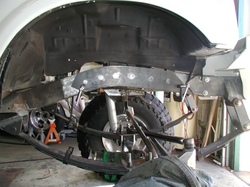
Been busy stripping the bracket and under coating off the PS rail. Here is the progress and a bit of future direction on this side.
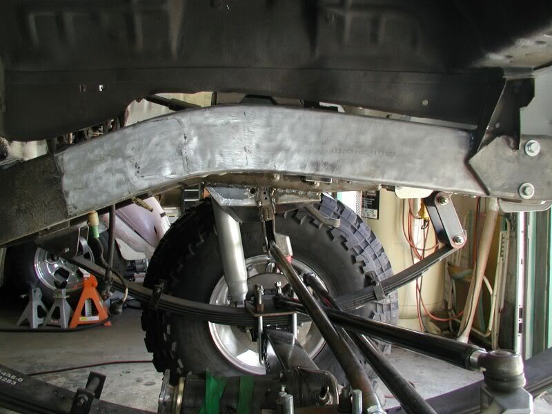
PS box plate with rosette weld holes.
Been busy stripping the bracket and under coating off the PS rail. Here is the progress and a bit of future direction on this side.
PS box plate with rosette weld holes.
Who is online
Users browsing this forum: No registered users and 20 guests