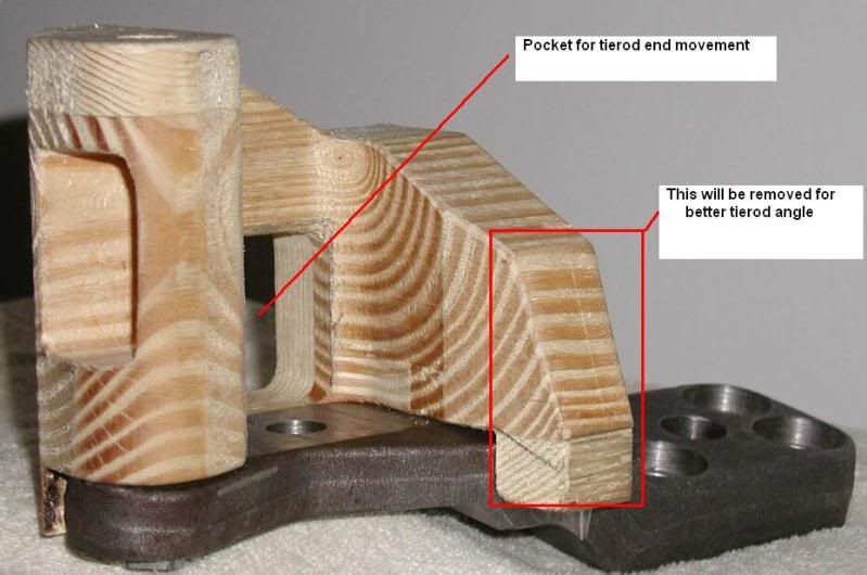
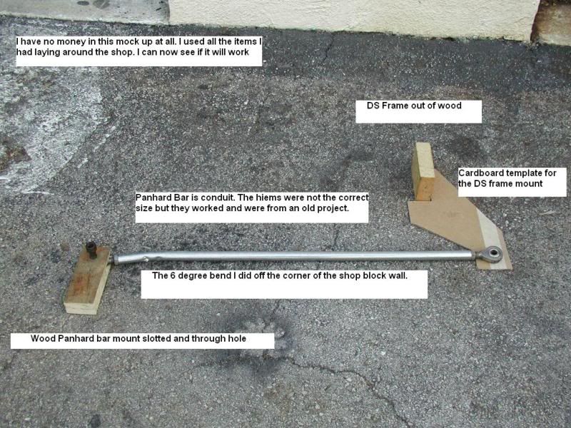
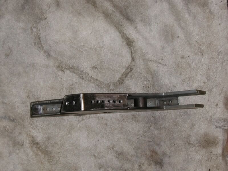
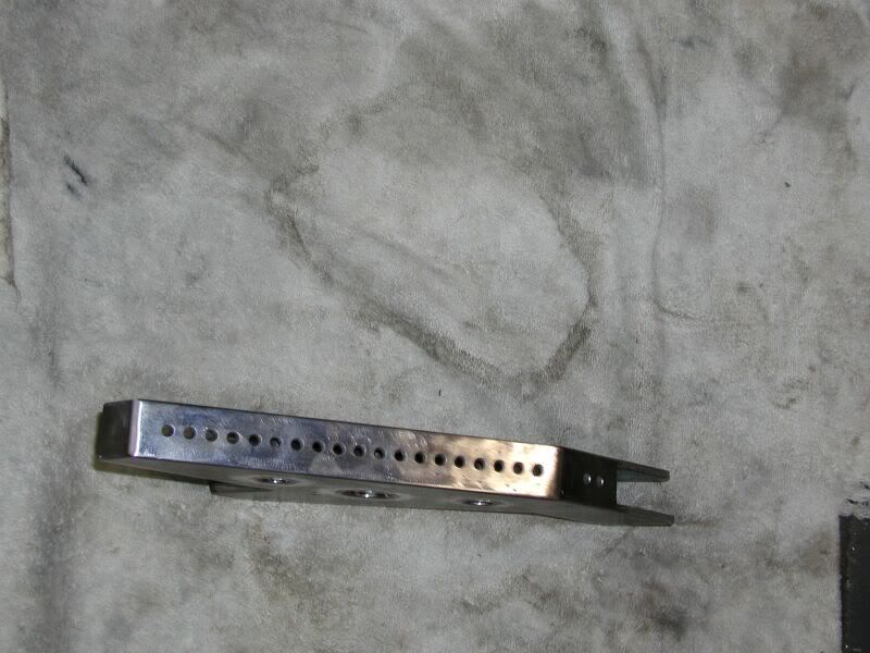
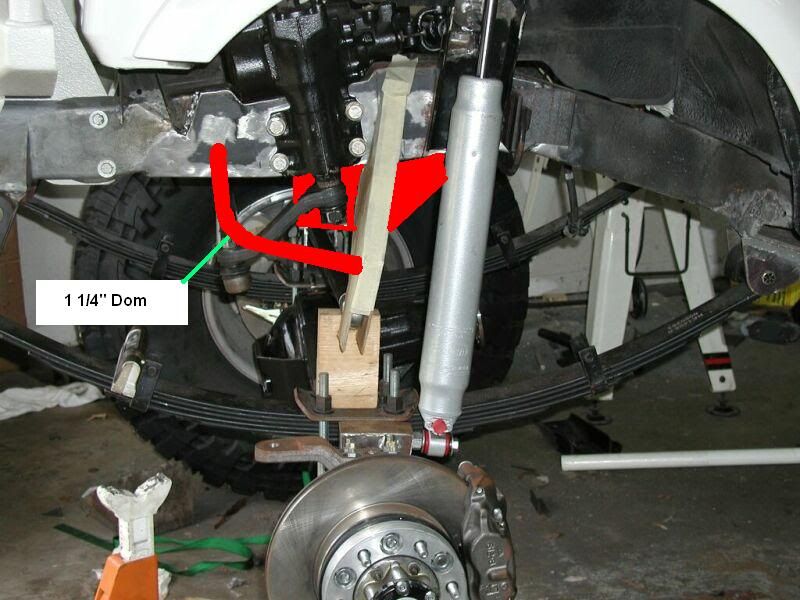
I even machine up my proto type pieces from wood first. Just to make sure they work out.
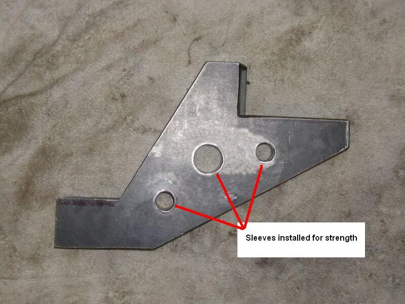
Wood Extended High Steer Arm
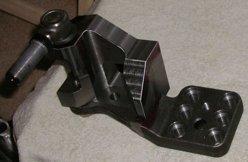
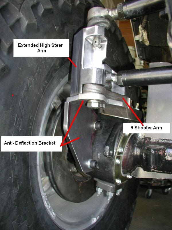
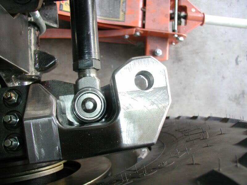
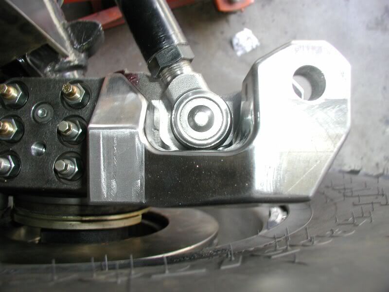
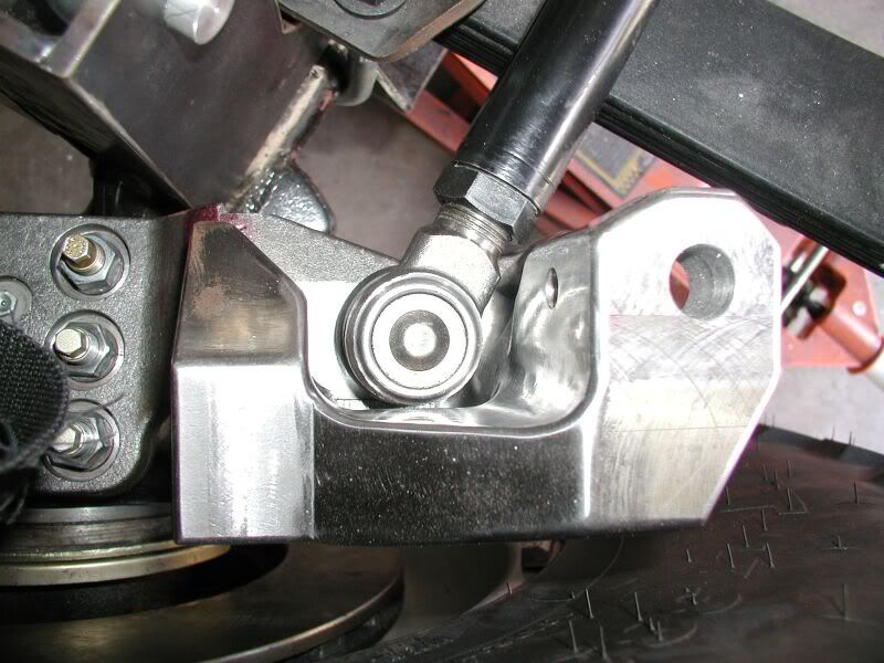
Finished Piece
chrome wrote:one of the best written threads i have seen in a long time
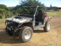
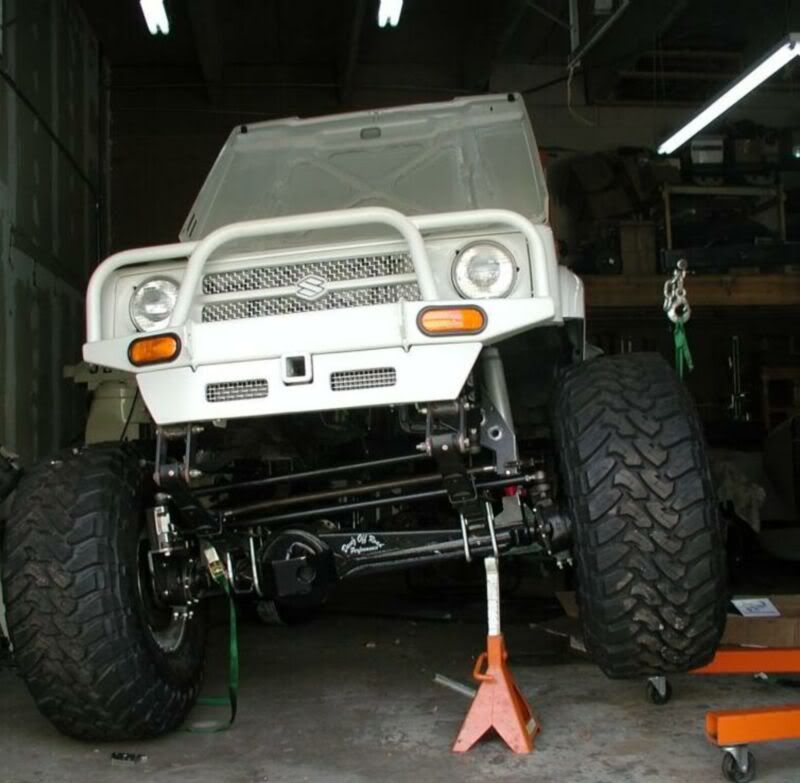
and that willys is pretty cool
Jafa wrote:Thats pretty damn cool! Nice fab skills, I'd expect nothing less from a fellow toolmaker and CNC jockey
Look forward to seeing some flex pics
rokhound wrote:I was going to add "I hope this not going for NZ cert with welded steering components" but when I actually opened my eyes I see you are in the US.
As Jafa said, real sexy fab
tomsoffroad wrote:As the others said. Thats awesome. Love it
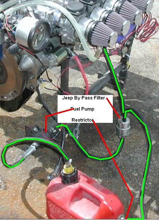
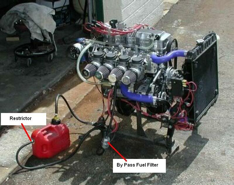
tomsoffroad wrote:I had a play around with quad carbs off a gxr1100 on a 1600cc Escort for a customer years ago (well I built the inlet manifold anyways) He had problems with fuel delivery
The bike carbs didn't like being feed fuel at pressure other than gravity pressure. I think he got around it with a surge tank in engine bay and gravity feeding the carbs. Not before he had a rather large fire tho
Food for thought
Users browsing this forum: No registered users and 11 guests