Re: 80 series factory rear locker issues
Posted: Mon May 04, 2009 7:53 am
The opinions and viewpoints expressed by users of Offroad-Express Forums are wholly their own and not necessarily those of Offroad-Express.
https://www.offroadexpress.kiwi:443/Forums/
https://www.offroadexpress.kiwi:443/Forums/viewtopic.php?t=12778
red-devil wrote:8) its a great site for info on the 80. been a member for a few years now.

red-devil wrote:wot were you seaching for.
there are writ ups on rear lockers the sun roof drain problem.
you do have to remember to think in yank as the locker is called
e lock sometimes

skid wrote:Heath wrote:why is http://www.1h8mud.com now a gardening forum? Yanks given up 4 wheeling?
hahahahahahahaha
try spelling it properly.............
http://www.ih8mud.com/


madaz068 wrote:After picking up a Factory elocker for the Prado, i have been searching for a way to wire it. I originally thought you get the factory switch and wire that into the 4wd system...... how wrong was I
Spent hours searching the net for info and while there is lots out there they all have different ideas and setups. I have used one based on a simple relay system (KISS)
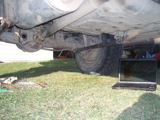
After searching the vehicle mine didnt have the factory wiring installed. Easy way to find out is look at the wiring for the suspension in the rear. If you trace it back it goes to just behind the rear large door on the side/top of the fuel tank (Prado LJ71)
If there is only the one plug like mine yours doesnt have the factory wiring. Dont worry i have the wiring to make it work
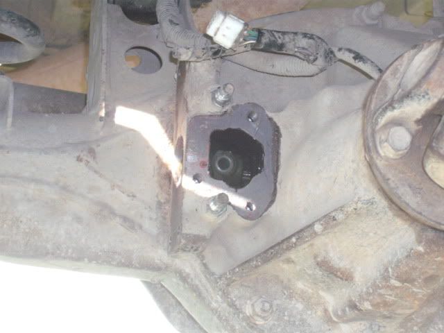
First make sure you get the factory wiring with the Diff. It will include the wiring for the shocks, i stripped the shock wiring out of mine as i have replaced the shocks. There is two plugs on top of the Diff a 6 pin (only 5 wires) and a 2 pin.
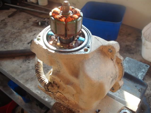
Top of locker
Locker wiring
Control Circuit
There are two connectors on the locker. There is a smaller 2-pin connector which connects to a switch that closes when the locker is actually locked, and a larger 5-pin connector which connects to the actuator motor and limit switches.
Pins 1 and 2 go to the motor. Applying +12v to pin 1 and ground pin 2 locks the unit. Reversing the polarity unlocks it.
Pins 3, 4, and 5 go to a limit switch, and are used to stop the motor before the mechanism reaches its mechanical limits. Pin 3 is connected to pin 5 unless the unit is locked. Likewise, Pin 4 is connected to pin 5 unless the unit is unlocked. Notice that while the unit is in transition between states, both pins 3 and 4 connect to pin 5.
So to lock the unit, put the alligator clip across pin 3 and pin 1. Apply +12v to pin 5 and ground pin 2. While the unit is transitioning from the unlocked to the locked state, pin 3 is connected to pin 5, and so pin 1 receives +12v. Once the unit determines that it has moved far enough to be locked, pin 3 becomes disconnected from pin 5, pin 1 no longer receives +12v and so the motor stops.
Likewise, to unlock the unit, simply put the alligator clip across pins 2 & 4 and apply +12v to pin 5 and ground pin 1. Once the unit is unlocked, the connection between pins 4 & 5 is broken, and pin 2 no longer receives +12v.
Using the limit switch will prevent the unit from reaching its mechanical limits and will avoid the problems I encountered.
The question has been raised as to whether the limit switch can handle the current drawn by the electric motor. That being unknown, the proper way to build a control circuit would be to use relays or transistors to handle the motor’s current.
The locker control circuit is fairly simple to build. The circuit below can use standard Bosch-type relays (Bosch pin numbers are shown on the diagram). These relays are inexpensive, rugged, and easy to find. Be sure that you are using double-throw relays, there are also double-pole SINGLE-throw Bosch-type relays that look similar but will not work. If you are using the Bosch-type relays, make sure that they have the 87a terminals on them, and not the 87b or double 87 terminals. See links below for more info on relays. Other 12 volt double-throw relays will work as well. The contacts should be rated 10A or higher.
The control switch is a momentary contact, normally open (off), SPDT switch. A regular toggle switch will work as well, however, the momentary contact switch is safer because if the actuator mechanism ever got jammed, a non-momentary switch would continue applying power to the motor and could burn it out or burn up your wiring. I know of a case where this happened and the wire actually burned a hole in the trucks carpet. It is also important to properly fuse the circuit and use properly-sized wiring. I am using a 6 amp fuse (could probabaly go even lower) and 18 gauge wire (some may argue for larger wire).
Using the momentary switch, you must hold it for about 1 second while the locker engages or disengages. If the control box is in the cab, you should hear the relays click off once the mechanism has reached its limit.
Locker Control Circuit:
Wiring Colours (LJ Prado's dont know about other lockers)
Pin 1 = Blue
Pin 2 = Blue/Orange strip
Pin 3 = Green
Pin 4 = Green/Yellow Strip
Pin 5 = White/Black Strip
Pin 6 = Red/Blue Strip
Pin 7 = White/Black Strip
Pins 5 and 7 join together just down from plugs
Purchase Parts
Went down to local auto sparky and purchased all the parts for $53 including 3 metres of 7 core cable.
Parts that i got
2 x Bosch 03322091650 relays
1 x Spark Shop Part number 32-120-S Tog Switch
3 Metres of 7 core cable.
Wiring
Scary part yes, but on the end of the wiring from the diff is a single 6 pin plug. Cut this off and you should be left with 6 wires. The colours are above. On mine i have wired like this into the 7 core cable (you can do your wiring how you want)
Pin 1 (Blue) into Blue
Pin 2 (Blue/Orange) into Yellow
Pin 3 (Green) into green
Pin 4 (Green/Yellow) into brown
Pin 5/7 (White/Black) into black
Pin 6 (Red/Blue) into red
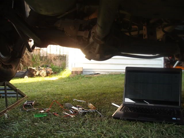
Now i need to goto truck and wire from the diff into the truck. I will post updates as i go.
