This is what a stock output shaft looks on a TJ (as you can see its very long for a short wheelbase vehicle and bent in my case).

To solve the problem, I got a slip yoke eliminator kit and a matching rear double cardan driveshaft from the US. The kit looked really beefy and well designed. The kit also allowed me to add about six inches to the driveshaft length. This is great because it allows better running angles on the u-joints. But best of all, the kit takes the slip joint from the output on to the driveshaft where it belongs.


When I got the kit, I called up a couple of shops to find out how much the labour would be. The answers I got were more along the lines “do you have instructions with the kit”? I was not prepared to pay someone else follow the same instructions that I had. So I decided to tackle the job myself this Saturday.
I will outline the steps involved below:
1. Secured the TJ with wheel blocks as I was not about to risk my life with just handbrake made by Jeep.
2. Put the transfer case into 4L.
3. Supported the engine and transmission with two axle stands and a scissor jack. Safety overkill, but its better to be safe.
4. Removed the four bolts of the transmission mount.
5. Put a hydraulic jack under the transmission skid to support the weight, primarily because I was working alone and did not want it to fall down and cause an injury. Again, safety first!
6. Removed the six bolts holding the skid to the frame and then slowly release the hydraulic jack. Nice and gentle removal of the skid.

7. Now I marked the front driveshaft and both end yokes with some paint. This was to make sure that when I assembled it back together, I did not rotate the yokes and possibly cause an out of balance driveshaft.
8. Drained the transfer case of oil before disassembling anything.
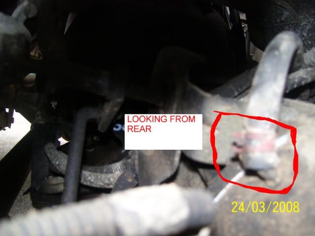
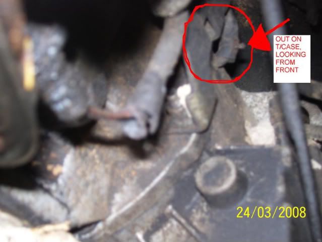
9. Removed the yoke from the front output shaft of the transfer case.
10. Removed the dust shield from the rear mainshaft. This was done by using a chisel to dent the dust shield collar area (where the rubber boot band was located) in two places at 180 degrees apart then prying the shield loose using a screwdriver.
11. Next removed the oil seal from the rear bearing housing.
12. Removed the rear shaft retaining ring using a pair of snap-ring pliers. I had a 9” pair and still struggled with it.

13. Undid the bolts and removed the tail housing from the rear case half. This housing contains the bearing and speedo gear. This exposes the oil pump that sits on the mainshaft and rotates and circulates oil as the vehicles is being driven.

14. Now comes the fun part, undid the bolts holding the rear half of the case. There is one bolt at the top that is different from all the others. It is a 10mm star shaped bolt. I cannot understand why New Process designers would do this, but it is there.
15. Once all the bolts are off, use two prying positions and pry the back half free. Be careful not to cause all the internal to fall out as that would make it difficult to see how things fit together.


16. Remove the spring from the top of the mode fork and keep it handy. It will be required at assembly time.
17. Then remove the front and rear shafts along with the drive chain. Put the front shaft and chain to a side. Take the rear shaft and remove the snap ring holding the main sprockets on it. Once that is removed, its an easy slide off the old shaft and on to the new shaft. Just be careful to make sure the everything goes back in the same orientation. It is possible to assemble the main sliding part to be assembled backwards (again a wonderful design concept).
18. As you can see the new mainshaft is so much smaller.


19. Installed the mainshaft assembly and mode fork into the case. The mode fork rod should be well lubricated before performing this step. The lubricated rod should slide through the range fork easily. Install the spring you removed in step 16.
20. Looped the chain around the main sprocket and front output shaft then installed the front output shaft through the bearing until it sat firmly.
21. Positioned the oil pump and pickup tube assembly into the rear case half. Ran a bead of a gasket sealer on the rear half and installed the rear case/pump onto the front case half. Be careful that the oil pickup tube does not come off the oil pump.
22. Installed the bolts, including the star bolt at the top.
23. Placed the tone wheel onto the mainshaft. Be careful that the tone wheel is not installed in the reverse position. You will note that the tone wheel will rest on top of the oil pump and spin easily. This is not an issue. Installation of the yoke nut will draw the shaft outward therefore sandwiching the tone wheel off of the pump surface.

24. Ran a bead of gasket sealer and installed the new rear bearing housing into position. Apply grease to the seal lip before positioning the housing into place.
25. Installed the 5 bolts to hold the rear housing in place.
26. Applied a small amount of gasket sealer to the back side of the yoke nut and in the threads before tightening it on to the shaft.
27. Installed the yoke nut and torqued it to 150 ft-lbs. The instructions say to torque it to 200 ft-lbs, but my torque wrench does not go that far high. I will be going to a shop to get this nut torqued properly before installing the rear driveshaft.
28. Installed the front yoke and torqued it to recommend 130 ft-lbs. Installed the front driveshaft.
29. Install the new speedo sensor into the rear housing and filled the case with Mopar ATF+4.
30. Installed the transmission skid plate back on.

This is where I have stopped. Next I will be installing the speedo recalibration unit to properly convert the new electronic signal to match Jeep signal. I will also be installing the new rear driveshaft.
I have test driven it to make sure that internals work and I can shift through 2H - 4H - N - 4L. It works fine, just needs a rear driveshaft.