I am looking to have my inlet manifold modified to rectify certain concerns I have about 1 and 6 starving of air volume if I add more fuel/boost.
By principal I understand that a 4.2 litre engine will induce then expel 4.2litres of air per revolution if all the pistons cycled together ie 2 stroke.
however they have staggered starts so it takes two full revolutions for all 6 pistons to cycle ie 4 stroke.
so by that account 2.1 litres of air is being induced per revolution.
I'm looking to adapt a factory manifold to a twin plenum design similar to audi and cosworth designed products.
The idea being that the air enters a tapered duct on top of the factory manifold then draws through into the larger volume manifold below via a slot the length of the manifold.
drawing through the slot should introduce the air as a sheet across the ports and the tapering of the duct shall keep the air velocity up across the length of the slot so that the volume of air is equal.
I tested this by putting a slit in an l&p bottles neck put the slit towards the ground and giving it a squeeze with the cap on.
resulting in a very even sheet of water being pressurised through the slit.
Next will be to measure the volume the factory manifold can contain,
I will consider the inlet ports down to the valves as fairly negligible as I want to firstly ensure the factory manifold has a safety margin in its volume to account for poor flow characteristics, imbalances and turbulence.
Multiplying our required air volume by the engines peak rpm we can then work out a flow requirement for the manifold.
say 2.1litres x 4000rpm = 8400 litres per minute required.
which in the old money is 8400 lpm/28.316846 litres in a cubic foot.
giving a flow requirement of 296 cfm.
The Australians all seem to be increasing the volume of there manifolds by 1.2 to 1.5 litres which assuming the factory one is at least 2.1litres would take them out to the 500cfm mark if they're running up to 4000rpm.
being that peak torque is down at 2500rpm I would therefore cap my desired rpm at 3200 for calculation purposes meaning I'd only really require 237cfm from the manifold otherwise I'd introduce a lag situation when throttling on and off and waiting for the plenums to fill before the turbo boosts.
Any thoughts upon this theory? excuse my rusty partial knowledge of fluid dynamics...
inlet manifold tech
inlet manifold tech
problems are only a problem if you not willing to learn how to find solutions
-
ChurchurDan
- Hard Yaka
- Posts: 574
- Joined: Sun May 12, 2013 7:49 pm
- Location: North Canterbury
Re: inlet manifold tech
Another consideration is that the air in the manifold is pulsing as valves open and close, this creates pressure waves moving backward and forwards through the manifold.
Have you considered splitting the manifold between cylinders 3-4 to create 2 plenums and thus reducing the pressure changes in each plenum as it will have a longer time between valve openings. Due to the firing order it will alternate between plenums.
Generally with forced induction runner length and plenum volume do not have a big impact on performance. Why not just put a tapered top on like everyone else as it is a simple proven concept.
-
Crash bandicoot

- Hard Yaka
- Posts: 2924
- Joined: Thu Dec 30, 2010 7:19 pm
- Location: Towing a hilux
Re: inlet manifold tech
nissan spent multi millions on r&d, there gtr plenum is probably the most efficient design for a factory inline six.
google it a study the shape of it.
google it a study the shape of it.
Waiter...there is a drought in my glass.

Re: inlet manifold tech
Would you not have to consider the increase in air pressure your turbo will provide from atmospheric. I had similar calculations on a thread awhile ago.
http://www.offroadexpress.co.nz/Forums/ ... 46&t=28239
http://www.offroadexpress.co.nz/Forums/ ... 46&t=28239
Men do not quit playing because they get old.
They grow old because they quit playing.
They grow old because they quit playing.

Re: inlet manifold tech
i would not get to fancy on theory.
tons of this has already been done, you have probably already read the long threads on patrol forum about it. i would just follow the advice there.
a lot of it will depend on if its just modding the manifold or building from scratch. where the IC is mounted etc.
how much boost are you running?
comparing petrol manifolds and diesel is not a great idea. simply because petrol ones tend to take vacuum conditions into account. where as turbo diesel is all about flow under boost.
Re: inlet manifold tech
not really too fussed on the raised height plenums or split banks
http://www.bufkinengineering.com/intake ... ic=27504.0
I had a good read through these two and had a jam with the l&p bottle just to test the theory and it impressed me with its effectiveness and simplicity.
the raised height manifolds are using a blanket approach by which oversupply rather than good design provides the safety margin.
I liken them to putting your hose on fan then trying to fill 6 cups in a line with the arse all dropping out of them in succession of your intake 142635 cycle.
so looking at our firing order we intake on number One then skip 2 pots to Four then one pot to Two then 3 pots to Six then 2 to Three 1 to Five then 3 to One to start the cycle again.
From the last point of induction we can see that air is having to be drawn furthest to cylinders 1 and 6 from the last point of induction vacuum but past the central air supply
another curious thing is the tb firing order is the inverse of the td's although it still sees the big air shifts dragging past the central air supply.
By utilising a tapered duct and full length slot to supply the air it will somewhat dampen the pulse within the inlet back and forth between intaking cylinders especially 1 and 6 as they will cause the most disturbance by drawing the air not only furthest from the supply but also furthest from the last intaking cylinder
problems are only a problem if you not willing to learn how to find solutions
Re: inlet manifold tech
I think turbo petrol and turbo diesel as far as manifold design both lend positive aspects to each other although the end result in both instances are for different reasons.
The audi principal for the twin plenum design is to get even air flow so that the optimum fuel mix can be acquired in a petrol engine,
the same principal for the desire for even airflow exists in diesel but for airs cooling effect on the pistons
ie diesel -even airflow, more fuel, more power, lower ecgs, safer running.
petrol- even airflow, optimum fuel mix, more power, safer running.
I enjoy the theory just as much as the finished product especially if it proves effective,
truck is standard with absolutely no mods as yet so I might go get a dyno done just to see what it lays out prior to swapping manifolds and then turbos when I grab the td05
problems are only a problem if you not willing to learn how to find solutions
Re: inlet manifold tech
interesting design. just not sure if it will be any decent gain over the usual intake mods.
Re: inlet manifold tech
as far as I can tell the gains are in the security you get from being able to increase boost/fuel whist getting even ecgs across all cylinders.
in petrols they are claiming big mid range increases in torque and driveability.
in petrols they are claiming big mid range increases in torque and driveability.
problems are only a problem if you not willing to learn how to find solutions

Re: inlet manifold tech
Good thread, this. I barely understand a word of it, but good thread nonetheless 
Something about putting L&P in a GT-R intake manifold
Something about putting L&P in a GT-R intake manifold
Re: inlet manifold tech

a little progress on this making the tapered duct from tube without rollers is satisfying
problems are only a problem if you not willing to learn how to find solutions
Re: inlet manifold tech


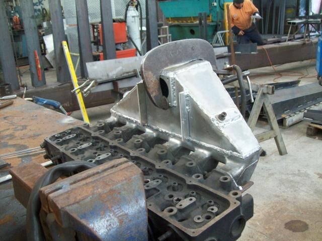
picked this up last night, couldn't be happier,
ducted plenum, pumped volume main chamber
6mm by 550mm slot down the duct into the manifold
and the head face skimmed all for $300
https://www.facebook.com/astreetcustomalloyfabrication
props to Lachlan for his hard work and great price
problems are only a problem if you not willing to learn how to find solutions
Re: inlet manifold tech
it will be interesting to see how it performs.
chuck a pic up on the patrol forums and see what they think.
i'm wondering if the slot will make to much turbulence.
chuck a pic up on the patrol forums and see what they think.
i'm wondering if the slot will make to much turbulence.
Re: inlet manifold tech
I'm not too worried about dyno figures as its a daily ,
but will put it on and do seat of the pants measurements when I bring the w/a back in a couple weeks.
also run the heat gun over the exhaust ports when I've towed a trailer for a bit just to see if the temps are even
but will put it on and do seat of the pants measurements when I bring the w/a back in a couple weeks.
also run the heat gun over the exhaust ports when I've towed a trailer for a bit just to see if the temps are even
problems are only a problem if you not willing to learn how to find solutions
Re: inlet manifold tech
Interesting concept.
Did you chamfer the edges of the slot?.
Did you chamfer the edges of the slot?.
Re: inlet manifold tech
glynn the chap that ran the mill just tidied them up square,
when the money allows i'll start on a mk2 version which will be bigger in the main plenum,
with a few more audi traits
when the money allows i'll start on a mk2 version which will be bigger in the main plenum,
with a few more audi traits
problems are only a problem if you not willing to learn how to find solutions

Re: inlet manifold tech
my lump. now sitting on my garage floor, new inlet gasket $12 STA auto parts.Awaiting to install it

Last edited by coxsy on Wed Oct 15, 2014 8:42 pm, edited 1 time in total.
89 safari, pto winch, 33x15 simexs. sliders,75mm lift . turbo intercoolered

Re: inlet manifold tech
What's the air velocity through that slot like? You have to be careful that it doesn't get too high otherwise you'll have high pumping losses.
Re: inlet manifold tech
the slot is 110% the surface area of the inlet pipe size being 2.5",
I would be pretty certain any pumping loss would be negligible given the air escape path aperture is larger than its approach aperture.
still waiting on a gauge and my w2a to install itself,
but once that's done i'll have some further data
I would be pretty certain any pumping loss would be negligible given the air escape path aperture is larger than its approach aperture.
still waiting on a gauge and my w2a to install itself,
but once that's done i'll have some further data
problems are only a problem if you not willing to learn how to find solutions
Re: inlet manifold tech
Good point, velocity should be lower. You do have 9 times as much wall in creating drag on the airflow now. You'll soon see if it makes any difference, any losses might be made up by the motor not blowing up.
Just figured why fluid pipes are round.
Just figured why fluid pipes are round.
Re: inlet manifold tech
i don't think extra wall aera will make much of an impact.
creating extra turbulence is the big thing. that can kill flow.
it will be interesting to see how it goes.
creating extra turbulence is the big thing. that can kill flow.
it will be interesting to see how it goes.
Re: inlet manifold tech
manifold has been on for quite a while now,
theres been no losses I can detect by seat of the pants measurements,
it definitely feels to have more torque in the low to mid range.
but again I want to see my egt figures before I go spouting great success.
and once I get that gauge it will be a matter of hooking up the w2a and the bush truck on the trailer and heading for the raglan divvy to tune the thing
problems are only a problem if you not willing to learn how to find solutions
Re: inlet manifold tech
got a pic of it on the truck?
it looks rather ugly..............
a bit of 3 and half inch pipe on top with center entry was what i was thinking of doing
it looks rather ugly..............
a bit of 3 and half inch pipe on top with center entry was what i was thinking of doing
Re: inlet manifold tech
of mine chap?
problems are only a problem if you not willing to learn how to find solutions
Re: inlet manifold tech
slidenyo wrote:of mine chap?
yea sorry dont mean to offend by saying how i think it looks, id rather like to see it in the vehicle
Re: inlet manifold tech
ah no worries function over form anyway ,
looks a bit silly atm as I haven't fitted the w2a yet, and I was waiting on the turbo for that job, which was waiting on the egt gauge, and then the right bends and clamp to turn up. but now I have all the parts and bugger all time to fit them even got a new light for the pushy just incase it takes me more then 4 days,
will take a pic tomorrow when I find the bloody camera the mrs has tidied away
looks a bit silly atm as I haven't fitted the w2a yet, and I was waiting on the turbo for that job, which was waiting on the egt gauge, and then the right bends and clamp to turn up. but now I have all the parts and bugger all time to fit them
will take a pic tomorrow when I find the bloody camera the mrs has tidied away
problems are only a problem if you not willing to learn how to find solutions
Re: inlet manifold tech
bolted my lump on this week good fit , feels smoother and faster pickup
89 safari, pto winch, 33x15 simexs. sliders,75mm lift . turbo intercoolered
Re: inlet manifold tech
How are those modified intake manifolds going?
Welds holding up?
Welds holding up?
Re: inlet manifold tech
yes the lump is going well ,the welding is holding up ,I only tacked the manifold up ,got the pro tig welder. to do the welding he had more hours on it than me.
may take it off and take a bit of the top to square it up with the engine slant ,maybe more if I get a top mount intercooler
may take it off and take a bit of the top to square it up with the engine slant ,maybe more if I get a top mount intercooler
89 safari, pto winch, 33x15 simexs. sliders,75mm lift . turbo intercoolered